The Electronics
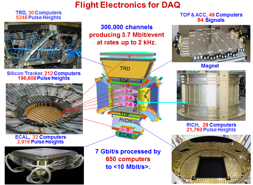
The AMS electronics system was mostly designed by the MIT group working with the AMS collaboration and constructed at CSIST (now the National Chung-Shan Institute of Science and Technology or NCSIST). As shown in Figure 1, it consists of 300,000 readout channels and 650 microprocessors that read out and control the entire detector. Extensive testing of all the electronics components and boards was carried out before construction to ensure the electronics would withstand the stresses of launch (static and vibration loads), rapid depressurization without outgassing under vacuum, and radiation exposure to about one krad/year while remaining electromagnetically compatible with the ISS and the sensitive detectors of AMS itself. In particular, components which met the performance and thermal requirements were subjected to heavy ion beam tests to quantify the rate of single event effects (bit flips or latch ups) expected in the ISS radiation environment and selected accordingly. After eight years of operation on orbit, the electronics system has performed optimally and only minor degradation of a few channels has been observed.
One of the main differences between a precision experiment at a particle accelerator and one in space is the thermal environment. In space, AMS orbits the Earth every 93 minutes. In addition, the Earth orbits the Sun once per year. The thermal environment changes both very quickly and with long-term trends. AMS has no control of the ISS orbit nor movements of the ISS solar panels and radiators. In addition, the ISS attitude is changed frequently, for example, for the docking and undocking of visiting vehicles (Soyuz, Progress, SpaceX-Dragon, Northrup/Grumman-Cygnus, etc.). However, as is discussed in the Thermal Operations, the temperatures must be kept within limits so that the detectors perform optimally, and, most importantly, so that no damage occurs to the detectors or the electronics. To achieve this, as indicated in Figure 2, a substantial amount of electronics was installed to monitor the 1118 temperature sensors and control the 298 heaters located throughout the 7.5 ton mass of AMS.
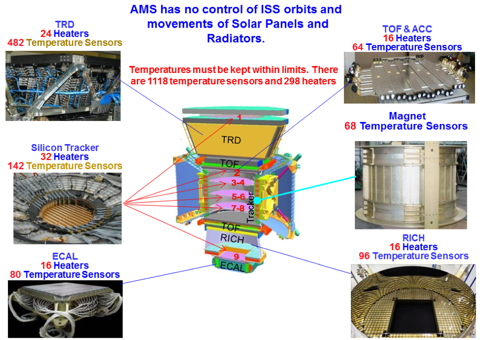
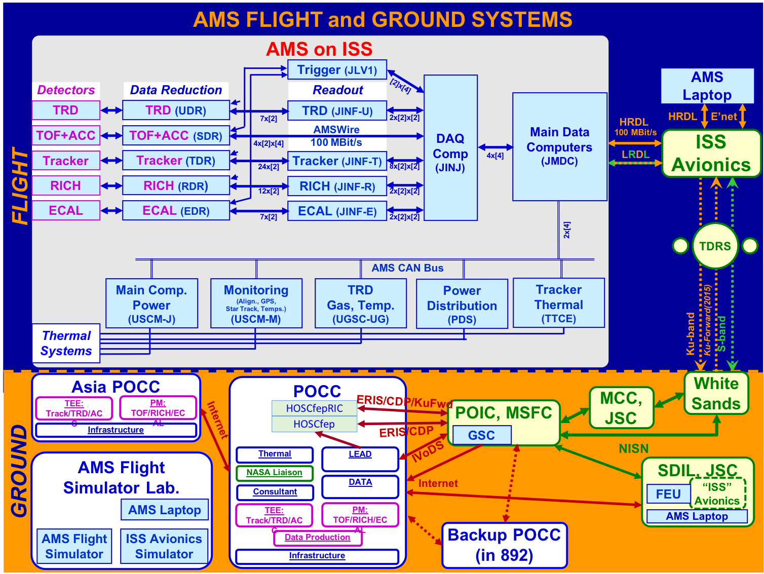
Figure 3 shows the data flow between the AMS detectors and the AMS monitoring and control systems on the ISS and the AMS POCC. Proceeding clockwise from the upper left, data from AMS is transmitted at an average rate of 10 Mbit/s over the High Rate Data Link (HRDL) on the ISS. Using the Ku radiofrequency band (Ku-band), it is sent up to geosynchronous Tracking and Data Relay Satellite (TDRS) and down to the White Sands Ground Terminal in New Mexico. To cover the ISS orbit, there are now five satellites in use. In the last three years, NASA has upgraded the facilities at the downlink station on Guam and this has improved the efficiency of Ku-band transmission. From Guam, the data rejoins the path at White Sands. From White Sands the data is directed over NASA networks to dedicated DOE-AMS computers located within the Payload Operation and Integration Center (POIC) at MSFC, Huntsville, AL, where the data are written on disk. Then the data are copied to the POCC at CERN over the Internet using the LHC GRID transatlantic connection. Commands from the POCC follow this path in reverse (counterclockwise, from the lower left) over networks, to the S radiofrequency band (S-band), and to the ISS Low Rate Data Link (LRDL). Both a complete and an immediate stream of monitoring data (temperatures, voltages, etc., at 30 kbit/s each) are also sent from AMS. In the case that the Ku-band is unavailable for an extended period, a smidgen of monitoring data, 10 byte/s, can be directed down the S-band which provides the minimum to maintain operations. A dedicated NASA Laptop is located in the crew quarters onboard the ISS which records and stores all AMS data for up to two months. Whenever there is a dropout anywhere along the chain, the missing data is recovered later from this AMS Laptop.
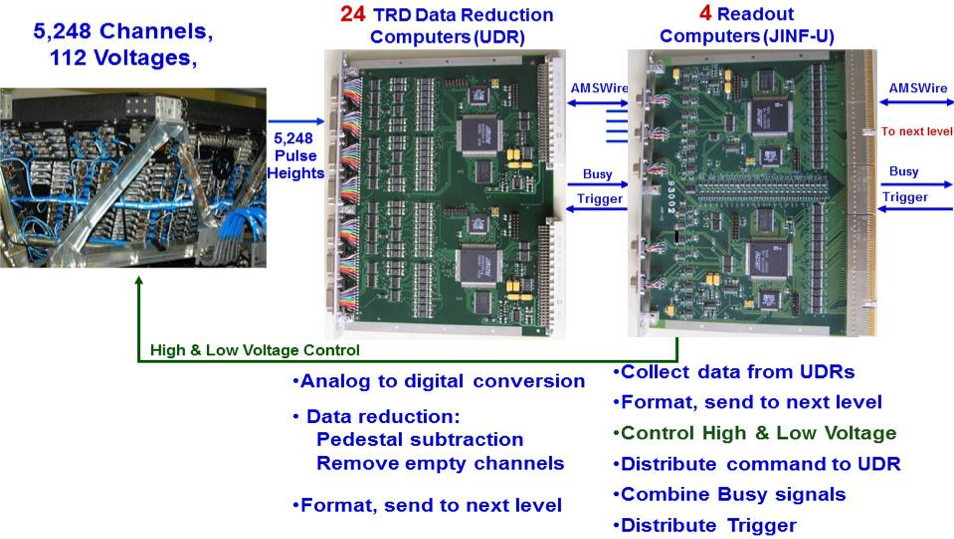
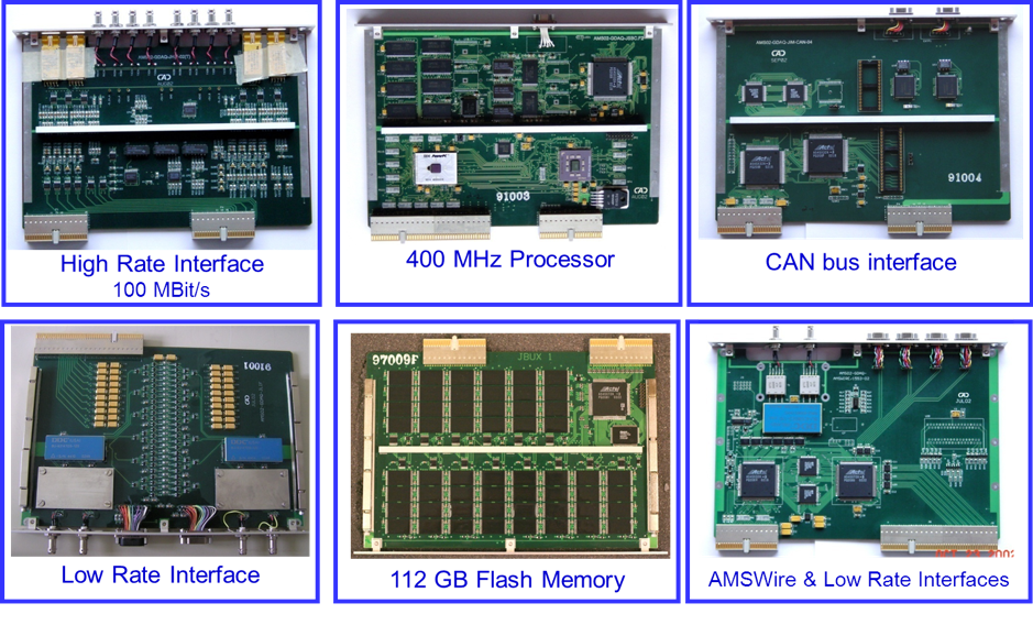
Figures 4 to Figure 14 show examples of the electronics designed and tested by the MIT group used on the ISS. These were mostly manufactured at NCSIST, Taiwan.
The TRD requires onboard processing via 30 computers measuring 5248 signal pulses, 482 temperature sensors and 8 pressure gauges. It also controls 24 heaters and valves as well as two pumps. This keeps the signal uniform to 1%. Two types of these computers (UDR and JINF-U) are shown in Figure 4.
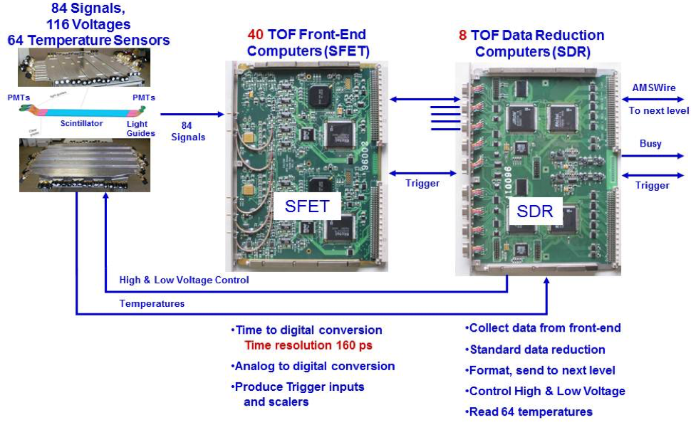
The TOF and Veto (or ACC) systems produce 88 signals and 44 50-MHz scalers. These are processed by 48 computers (SFET, SDR) shown in Figure 5. Proper operation allows the TOF system to have a resolution of 160 picoseconds for $Z=1$ particles and the Veto counters to exclude transverse particles with an efficiency better than 0.99999.
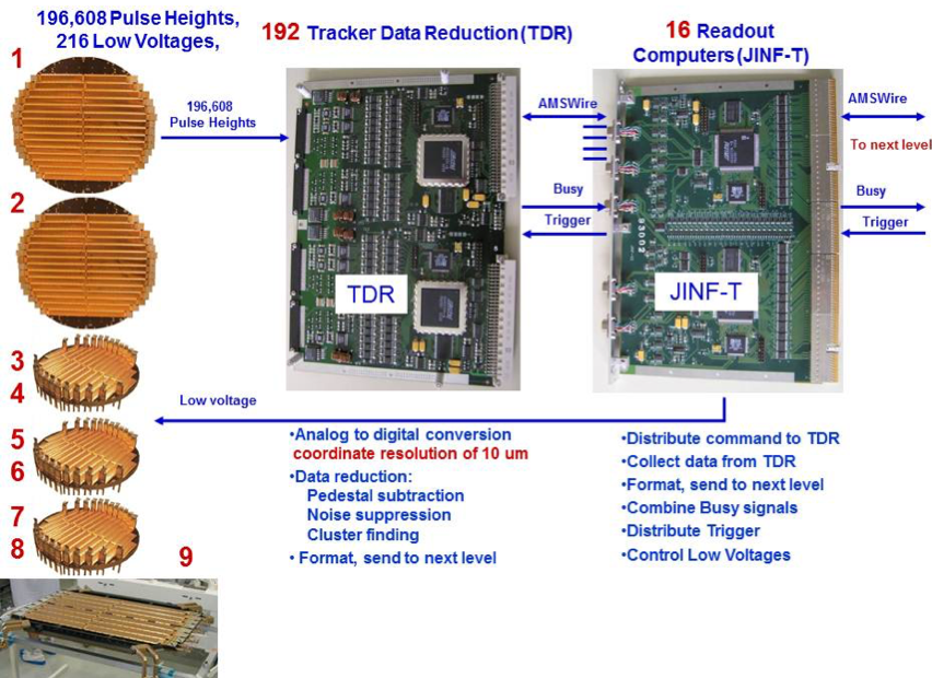
The silicon tracker produces 196,608 pulses. These are read out by 208 computers (TDR, JINF-T), shown in Figure 6. This allows the Tracker to provide a 3-dimensional reconstruction of the particle trajectory with micron level resolution.
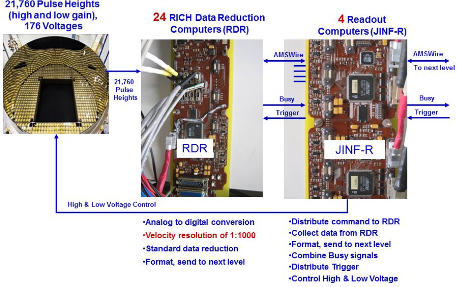
The RICH has 10,880 photosensors, which produce 21,760 high and low gain signals. This allows the detector to be sensitive at the single photoelectron level and provide a velocity resolution of 0.1%. The RICH signals are processed by 28 computers (RDR, JINF-R), see Figure 7.
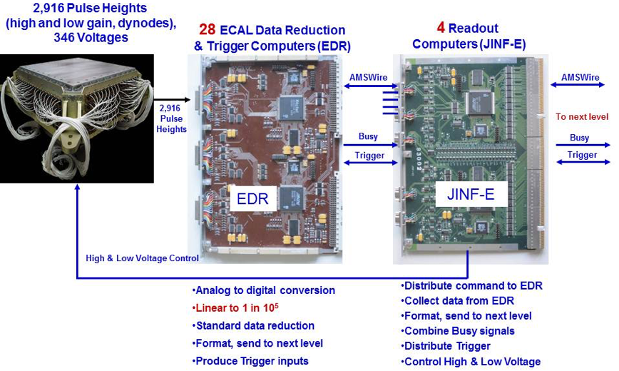
The ECAL produces 2916 signals. These are processed by 32 computers (EDR, JINF-E); see Figure 8. The fine granularity of the read-out allows the ECAL to have a linear response over five orders of magnitude, from 10 MeV to 1 TeV. This is required for the ECAL energy resolution of 2-3% for electrons and photons at energies above 10 GeV.
The trigger processor (JLV1, see Figure 9) collects fast inputs from the TOF, Veto, and ECAL; combines them according to various physics goals; and distributes a trigger signal to all the detectors to start their readout cycles. The coincidence of signals from the four TOF planes together with the absence of coincident signals from the ACC provides a $Z=1$ trigger. The coincidence of the four TOF planes with a signal from the ECAL and no anticoincidence requirement is also used to trigger electrons and positrons. For larger $\mid Z \mid$, a dedicated set of higher threshold signals is formed within the SFET boards and their coincidence along with the absence of signals from a specified number of ACC counters forms a dedicated trigger.
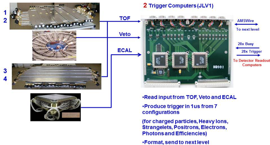
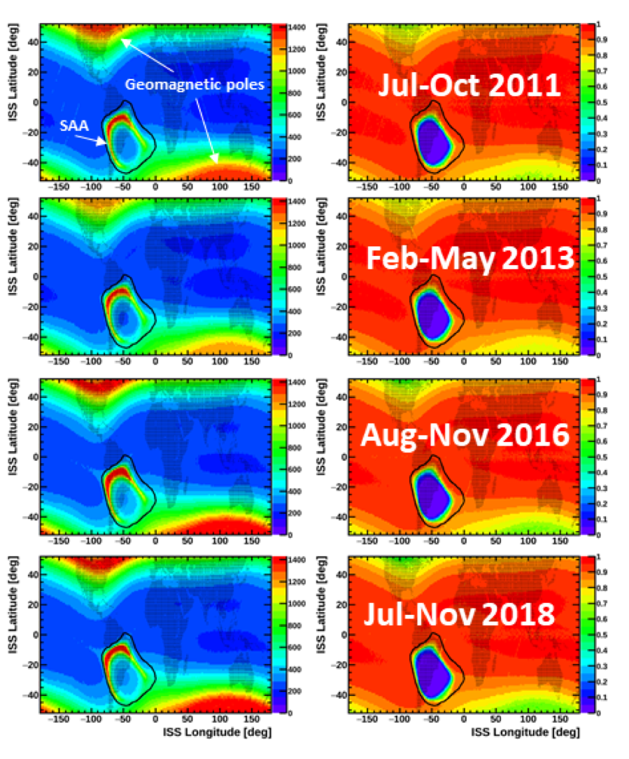
Figure 10 shows the two key parameters which affect the data acquisition (DAQ) on orbit. In the left column is the rate at which cosmic rays are measured and, in the right column, the efficiency, or live-time, which reflects the fraction of time that the electronics are ready to read out new events.
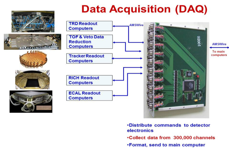
After collection and reduction, the data from all the detectors are combined in one of four redundant DAQ computers (JINJ); see Figure 11.
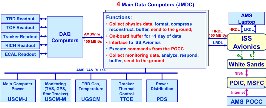
All of these computers send data to, and receive commands from, the four redundant main data computers (JMDC), see Figure 12, which in turn interface to the ISS electronics (often called avionics). The interfaces between AMS and the ISS require detailed knowledge of the ever-changing ISS avionics. The computers were at least 10 times faster than a “standard” NASA computer when they were built. The different subsystems of the JMDC are shown in Figure 13. The JMDC was designed to be reprogrammed from the ground to optimize the performance of AMS and to match upgrades by NASA to the ISS hardware and software.
The AMS Laptop provides the primary backup for AMS data (with disk swaps, it can store 2 months of AMS data) as well as an alternate command route to AMS. It is shown in Figure 14. The team in the Payload Operations and Integration Center (POIC) at MSFC organizes that the astronauts change the second drive on the AMS Laptop two times a year. The used hard drives are kept onboard as spares. The AMS Laptop runs a customized operating system and application programs, which were developed, tested and are maintained by the MIT group.
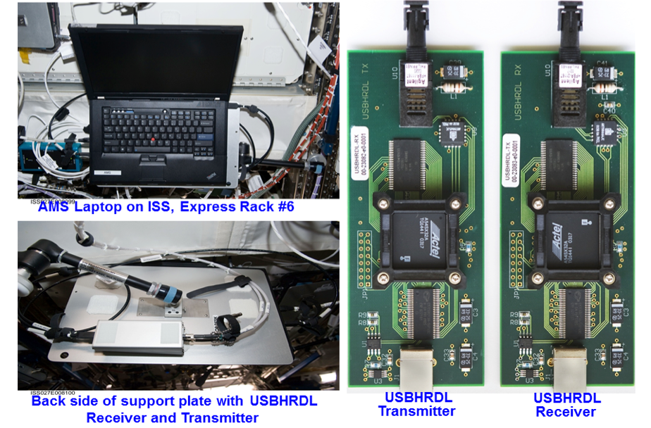
The NASA-provided laptop has worked well over the past eight years. It has had several hardware problems, notably rebooting itself about once a month and semi-annual disk crashes, though these have been quickly recovered by the experts working from the POCC and the astronauts on orbit, respectively. It is an IBM Thinkpad T61P model and NASA is replacing this computer on the Space Station by a new HP ZBook. After extended development and test, particularly of the USB-HRDL interfaces, the new AMS Laptop software is ready for new ZBook laptop. The new software is being manifested by the NASA AMS Program Office to reach the ISS in the summer of 2019 on the flight SpaceX-18. Once it is delivered, the crew will load it onto a new laptop.