Thermal
Thermal control is one of the most challenging tasks in the successful operation of the AMS experiment. AMS temperatures are changing continuously. The overall Thermal Control System of AMS must be monitored by the Thermal Team 24 hours a day and is one of the most critical positions in the AMS POCC. It is monitored continuously and exclusively at CERN.
The thermal environment on the ISS is constantly changing which impacts AMS operations and has the potential to damage AMS. Variations of the thermal environment include:
- The solar beta angle (β),
- The solar constant,
- Earth infrared radiation,
- Earth albedo (reflected sunlight).
NASA provided AMS with a detailed thermal model which included the above variables before launch.
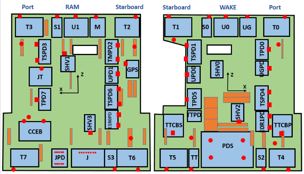
The AMS detector was designed and built with 1118 temperature sensors to ensure that components operate within safe thermal limits and a system of 298 thermostatically controlled heaters which are enabled or disabled for this purpose. Figure 1 shows the approximate locations of the most important temperature sensors inside AMS. The TRD and Tracker systems have their own thermal control systems.
Based on extensive tests of the detectors and electronics in Thermal Vacuum Chambers during the construction of AMS, we obtained Table I, which gives the most important temperature limits. Destructive limits are temperatures beyond which the components could be damaged. Alarm limits (or Operational Limits) are temperatures beyond which manual action must be taken to protect the detector component.
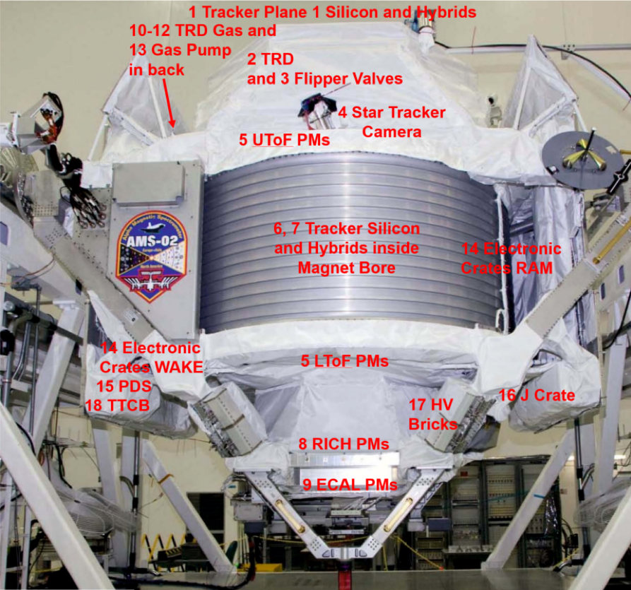
Table I. Examples of AMS Temperature Limits (in C) of AMS Detectors 1 to 23.
|
Detector Element |
Warning Limits |
Alarm (Operational) Limits |
Destructive Limits |
||||
|
|
Low |
High |
Low |
High |
Low |
High |
|
|
1 |
Tracker Plane 1 |
-15 |
+25 |
-20 |
+25 |
-20 |
+40 |
|
2 |
TRD |
0 |
+35 |
-20 |
+40 |
-25 |
+40 |
|
3 |
TRD Flipper Valves |
+10 |
+35 |
+5 |
+40 |
-5 |
+40 |
|
4 |
Star Tracker Camera |
-15 |
+45 |
-20 |
+50 |
-40 |
+60 |
|
5 |
ToF Phototubes |
-25 |
+30 |
-30 |
+35 |
-35 |
+42 |
|
6 |
Tracker Silicon |
-5 |
+20 |
-10 |
+25 |
-20 |
+40 |
|
7 |
Tracker Hybrids |
-5 |
+20 |
-10 |
+25 |
-20 |
+40 |
|
8 |
RICH Phototubes |
-25 |
+45 |
-30 |
+50 |
-35 |
+60 |
|
9 |
ECAL Phototubes |
-15 |
+35 |
-20 |
+40 |
-30 |
+50 |
|
10 |
TRD Gas Valves |
+10 |
+50 |
+5 |
+55 |
-20 |
+65 |
|
11 |
TRD Gas Xenon Tank |
-15 |
+60 |
-20 |
+65 |
-51 |
+65 |
|
12 |
TRD Gas CO2 Tank |
-15 |
+60 |
-20 |
+65 |
-73 |
+65 |
|
13 |
TRD Gas Pumps |
+10 |
+35 |
+5 |
+40 |
+5 |
+40 |
|
14 |
Electronic Crates |
-15 |
+45 |
-20 |
+50 |
-40 |
+80 |
|
15 |
PDS Electronics Boards |
-20 |
+43 |
-25 |
+48 |
-40 |
+80 |
|
16 |
J Crate Electronics Boards |
-15 |
+60 |
-20 |
+65 |
-40 |
+80 |
|
17 |
HV Bricks |
-15 |
+45 |
-20 |
+50 |
-35 |
+65 |
|
18 |
TTCBs |
-15 |
+45 |
-20 |
+50 |
-35 |
+65 |
|
19 |
GPS |
-15 |
+55 |
-20 |
+60 |
-40 |
+70 |
|
20 |
USCMs |
-15 |
+55 |
-20 |
+60 |
-40 |
+80 |
|
21 |
ToF SFEC Boards |
-35 |
+75 |
-40 |
+80 |
-55 |
+80 |
|
22 |
Tracker Alignment |
0 |
+30 |
-5 |
+35 |
-25 |
+50 |
|
23 |
Star Tracker Electronics |
-15 |
+45 |
-20 |
+50 |
-40 |
+80 |
Most of the AMS power dissipation takes place on the AMS main radiators, shown schematically in Figure 2, where 1500 W from the electronics crates radiates into space. Each of the indicated temperature sensors on the crates and on radiator panels is dual-redundant. The colored rectangles show the locations of thermostatically controlled heaters.
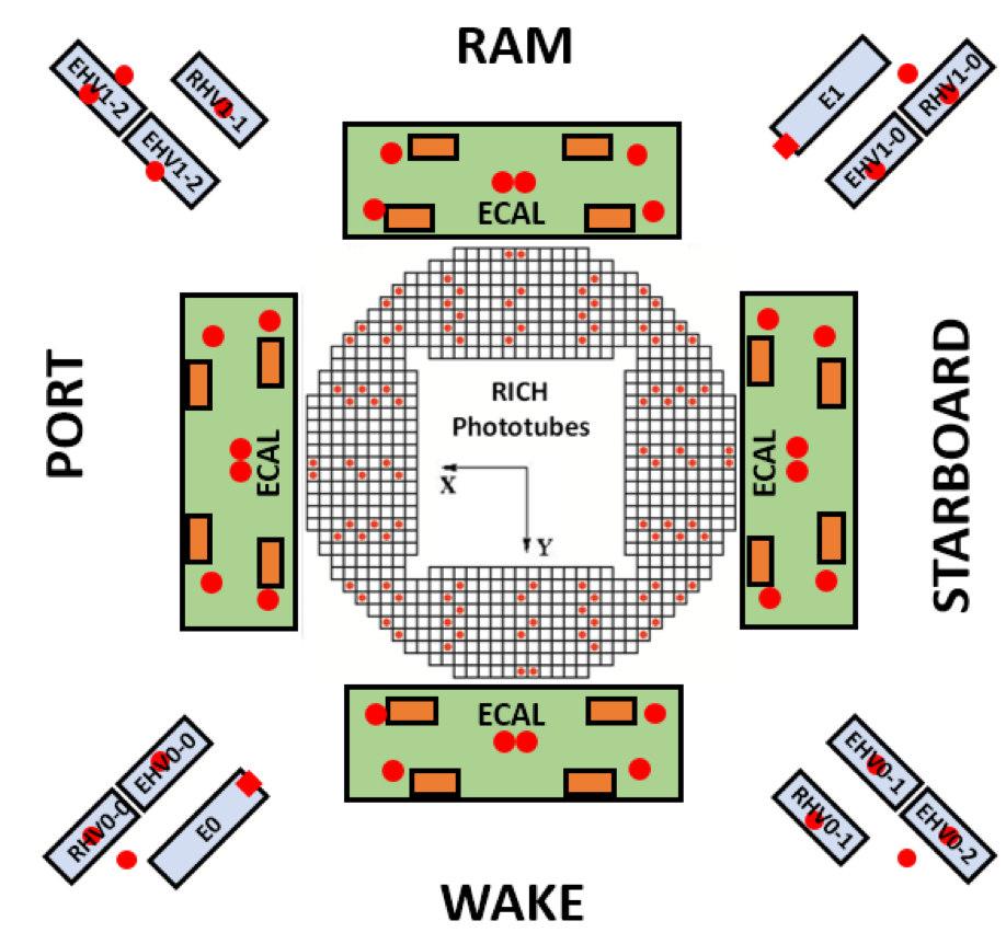
Temperatures of the readout crates and high voltage crates for the RICH and ECAL, located in a different thermal environment on the Lower Unique Support Structure (LUSS), are also individually monitored, as shown in Figure 3.
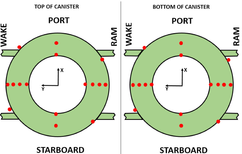
The aluminium canister, which supports the permanent magnet and contains the inner silicon tracker in its bore, has its own array of temperature sensors, shown in Figure 4.
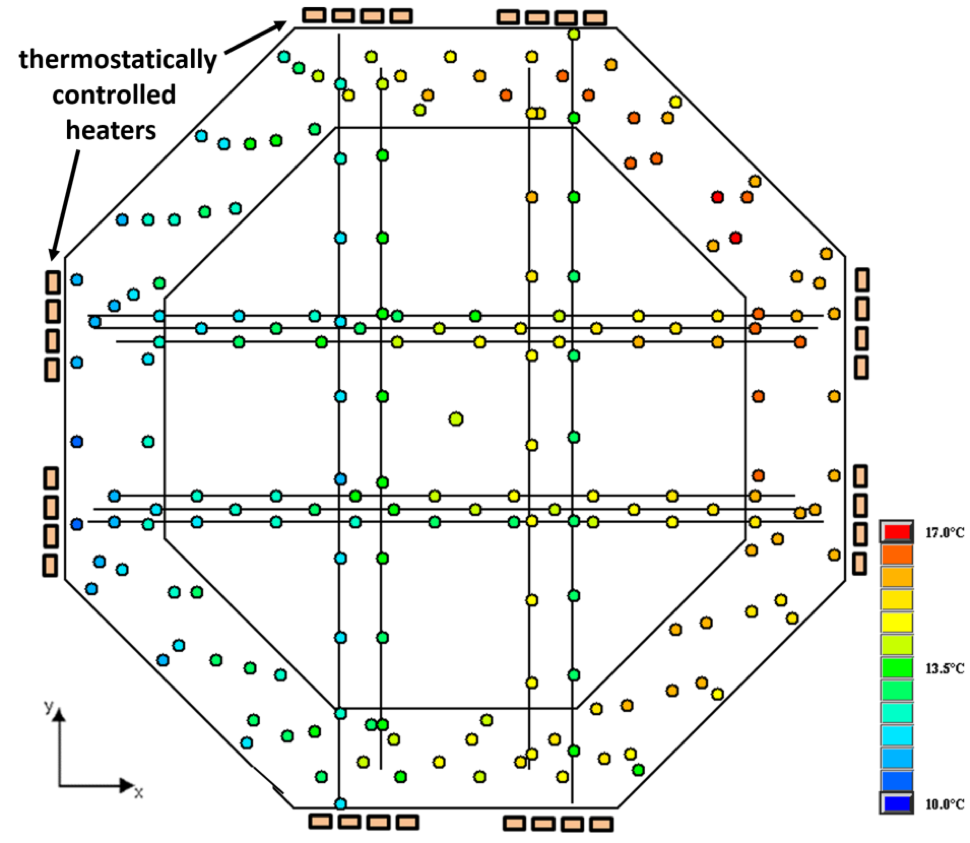
There are several hundred temperature sensors inside the Transition Radiation Detector (TRD) to monitor the gas density (see Figure 5).
Contributions from Shandong University to the AMS Thermal Control System
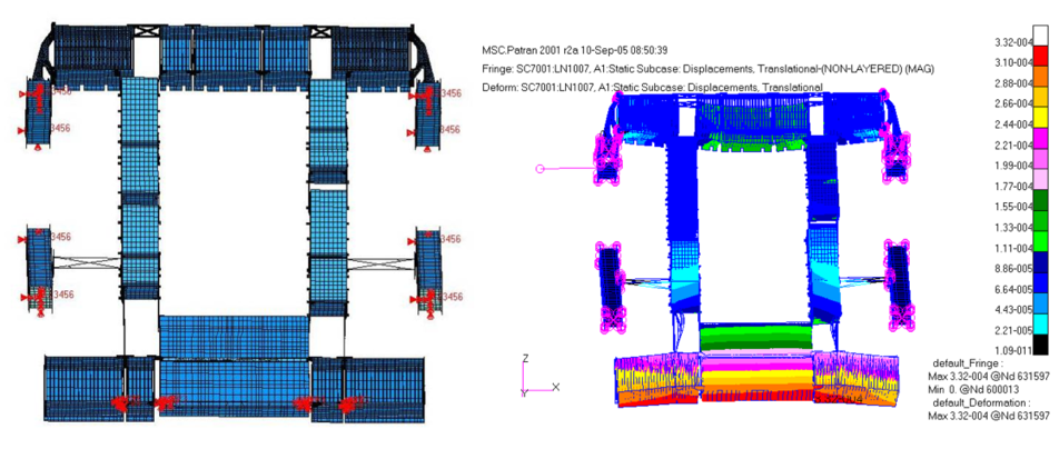
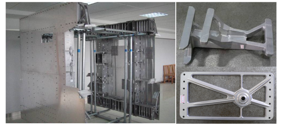
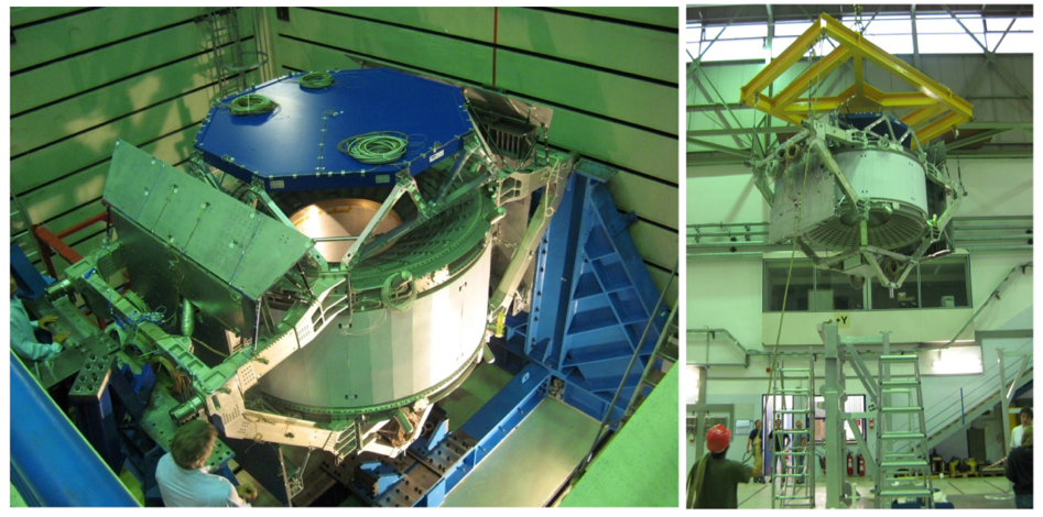
Collaborators from Shandong University under the leadership of Professor Q. Sun made the major contribution in the design, construction, and testing of the thermal system, and take nearly all the Thermal shifts. Shandong University did the thermal and mechanical calculations for the flight radiators (Fig. 6), and for a structural test article (STA), which they built (fig. 7.). It successfully passed tests with the entire AMS in Munich (Fig. 8). The more complicated parts of the radiator STA are on orbit with the AMS flight model. SDU also took a major part in the AMS thermal vacuum test at the European Space Agency’s test facility, ESTEC at Noorwijk in the Netherlands.