The Transition Radiation Detector (TRD)
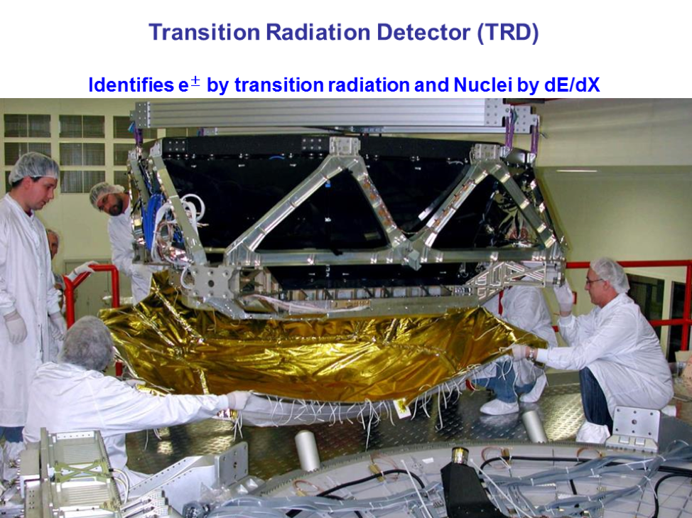
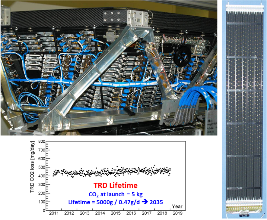
The Transition Radiation Detector (TRD) uses transition radiation to distinguish between electrons and protons. It consists of 5248 proportional tubes of 6 mm diameter with a maximum length of 2 m assembled in 16-tube modules. The 328 modules are mounted in 20 layers. There are 12 layers of proportional tubes along the y axis located in the middle of the TRD and, along the x axis, four layers located on top and four on the bottom. To differentiate between protons and electrons in the TRD, signals from the 20 layers of proportional tubes are combined. This provides efficient separation of the antiprotons and protons from electrons and positrons. Figure 1 shows the installation of the TRD. Figure 2 shows details of the TRD construction.
Gas for the 5248 proportional tubes is supplied from storage tanks with 5 kg of CO2 and 49 kg of Xe. Figure 12 also shows that, in eight years in space, there is no detectable leak. The loss of CO2 is due to diffusion at a rate of 0.47 g/day. The loss of Xe is negligible. This assures that the TRD will be operational in space for more than twenty years, until 2035.
As shown in Figure 3, when proton pass the tubes, it leaves $dE/dX$ signal. For positron and electron, due to there high Lorenz factor, they will emit transition radiation.
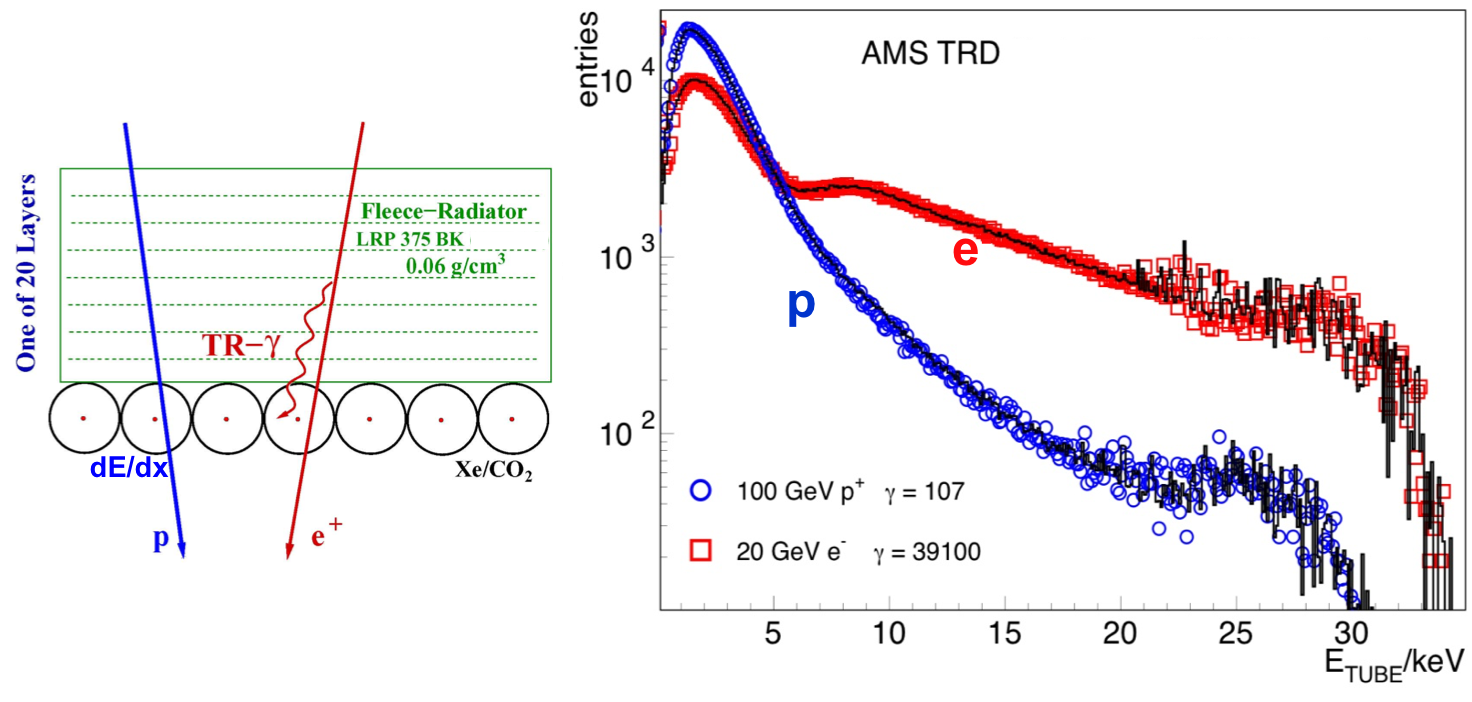
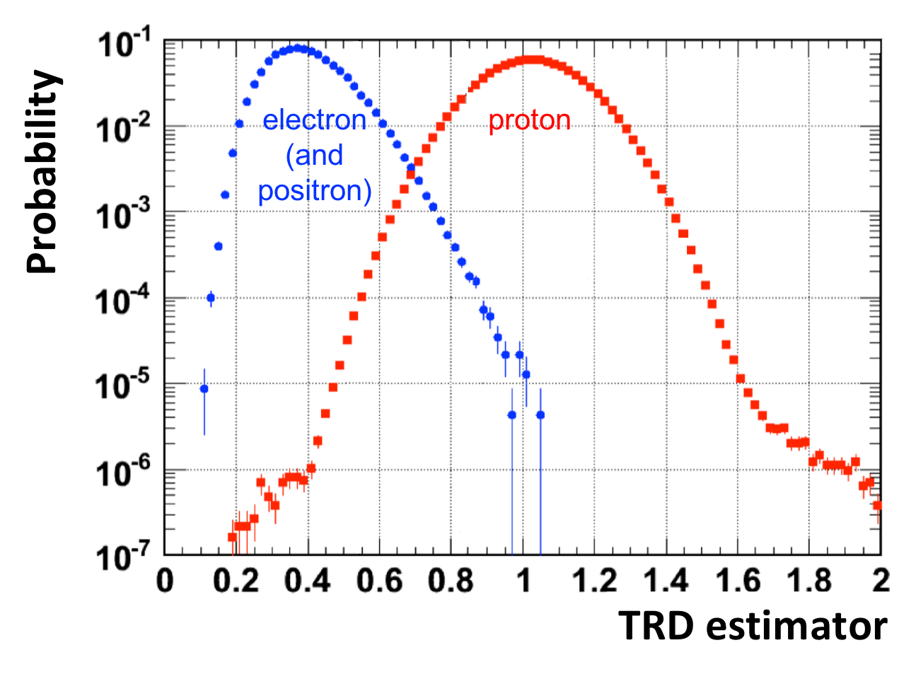
Figure 4 shows that TRD estimator combines the measurement from 20 layers of TRD to separate positrons and electrons from protons.
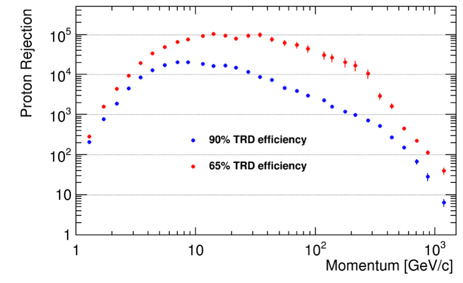
The operation of the TRD is continuously monitored and controlled by the TRD group. This includes daily high voltage adjustments on a module-by-module basis and monthly gas refills to keep the gas gain nearly constant. In addition, the calibration of individual tubes is performed regularly. This continuously maintains the electron to proton separation from the TRD at the 103 level, as shown in Figure 5.